


Installation Rules and Bits Part 2
13/07/08
OK, in part one we started at the back end, lets move to the front and discuss the bits up there.


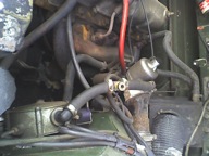
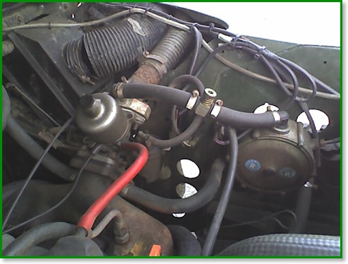
The reducer needs a constant supply of warm water, and you need to be careful that this is not subject to interruption if the heater is turned off. There are two water connections provided for this (the small ones top and bottom of the OMVL unit, lower left and right on the Romano) and these are normally tee’d into the heater circuit.

So far, and for most of the rest of this article, I’m only talking about mixer systems - mostly because that’s all I’ve dealt with so far. I’ll sidetrack a little and mention the alternatives and the key differences.
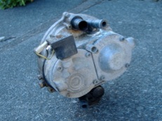
For newer vehicles it’s normal to use vapour injection - the gas is converted to vapour just like the mixer systems, but the reducer is different (it supplies pressurised vapour) and the vapour is injected into the inlet manifold in a manner very similar to petrol injection.
Much less common is liquid injection. Here the propane is kept liquid all the way to the injectors, and this requires a pump immersed in the liquid in the tank. The problems of keeping the propane liquid with the heat in the engine bay are not trivial and these systems can be problematic - the pumps are also expensive if the adverts on eBay are anything to go by !


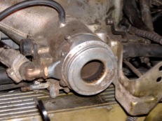
At this point I’ll dispel a commonly held misconception. The reducer does not push the gas through, the mixer pulls it.
The relation between airflow and ‘suck’ is fairly linear over a wide range (see this later article), so it is possible to have a fixed setup with nothing more than a manual power valve - as can be seen in the vapour hose on the land Rover pictured above. The power valve simply restricts the flow of gas, so you can adjust the gas flow to match the vacuum produced by the mixer.

If we are using a manual valve like this, a system known as ”Open Loop”, then the remaining items are a switch and safety cutout. The simplest approach is to use a ”Carb Switch” or “Injection Switch” (depending on the petrol system present) which combine both functions. A carb switch also provides a useful additional function which makes changing from gas to petrol a lot easier - I’ll cover this in a later article on using the systems.
CoP11 is very clear on this, there MUST be a safety cutout that stops gas flow when the engine is not running. This can be based on manifold vacuum, oil pressure, or ignition pulses - the commonest is to use ignition pulses to detect the engine running.
My preference is to use a ”Closed Loop” controller on most conversions - these use a Lambda probe to detect the air-fuel mixture and automatically adjust it as you drive. These make setup of the system a LOT easier - as will be seen in a later article on adjustments, getting a closed loop system “just right” can be a bit fiddly. There are many different systems around, some of them have a closed loop controller as a separate function in a box and still require an injection switch and/or safety relay. I usually fit the AEB Leonardo unit which combines injection switch, safety switch, closed loop controller, and fuel gauge into one box (AEB now have the Galileo El which combines all this with a 4 cyl injector emulator - and still in one box.)

So that’s all the major components, all that’s left is to plumb it up, wire it up, set your mixture - and enjoy !